
NOTE: The below build guide is a work in progress. If you find errors, please let me know via the contact us page.
1. Take Inventory
Make sure nothing is missing. Note that some parts will arrive pre-assembled to protect them during shipping. You should have:
- 1x PCB
- 1x Plate
- 1x Case Upper Half
- 1x Case Lower Half
- 1x Knob
- 8x Rubber Feet
- 12x M2.5×4 button head screws (for mounting the plate to the upper half of the case. These come installed for shipping)
- 12x M2.5×14 button head screws (for screwing the upper half and lower half of the case together. These come installed for shipping)
- 4x M2 button head screws (for mounting the USB daughter board in the lower half of the case)
- 1x M2.5 set screw (for the knob)
- 1x Encoder
- 1x Cable (for connecting the PCB to the USB daughter board)
- 2x Allen Wrenches
Optional, for hotswap PCBs:
- 17x aluminum spacers
- 17x M2.5×10 button head screws
- 17x M2.5 nuts
Optional, if purchased separately:
- 4x riser feet
- 4x M3 flat head screws
- 1x Allen Wrench
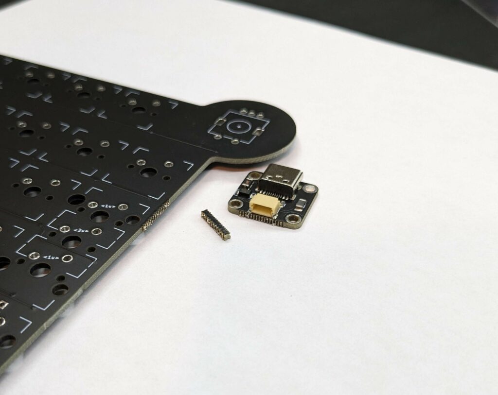
2. Prepare the PCB
Remove the USB Daughter board from the PCB. It will break off at the perforations, but may leave some material behind. Use pliers and/or a file to remove any remaining perforated PCB Material from both the daughter board and keyboard PCB, as it may impact the side of the case when assembled.
If you purchased a hotswap PCB, please read the Hotswap addendum, part 1
Connect the daughter board to the PCB using the supplied cable.
Flash the firmware onto the PCB. Plug in a USB-C cable, and the PCB will show up as an external storage device. Simply drag and drop the firmware into the storage device, and the firmware will be loaded. To enter bootloader mode, hold down the button on the back of the PCB labeled BOOTLOADER, then press and hold the button labeled RESET for 3 seconds, then release both buttons.
Using a jumper wire, confirm that all of the keys work as expected.
3. Assemble the PCB
Install your stabilizers where needed. Positions of the stabilizers will depend on your selected layout. Installation method will depend on your choice of stabilizer.
Install and solder the encoder into place.
Install plate & switches where needed. If you purchased a hotswap PCB, please read the hotswap addendum, part 2.
4. Assemble the case
Place the adhesive-backed rubber feet into the necessary locations, either directly onto the case, or onto the case and the optional 7 degree feet risers.
Install the USB daughter board into the lower half of the case. It is easier to plug the cable in before installing the daughter board. The USB plug faces down, towards the bottom of the case. Use the supplied 4x M2 screws. Use a small drop of light oil on the screw threads when you install them.
Attach the plate and PCB assembly onto the upper half of the case. Use the supplied M2.5×4 button head screws. Use a small drop of light oil on the screw threads when you install them.
Plug the cable into the bottom of the PCB, and attach the upper half of the case to the lower half of the case. Use the supplied M2.5×14 button head screws. Use a small drop of light oil on the screw threads when you install them.
Install the knob onto the encoder. Apply a small drop of light oil onto the M2.5 set screw, and thread into the knob until you can see it slightly protruding into the hole on the bottom of the knob. Align the screw with the flat on the encoder shaft, and drop the knob onto the encoder. Tighten the set screw to hold it in place. Be careful not to over tighten, very little pressure is needed to hold the knob in place.
Install keycaps.